A quick note about the power. In the schematic it states that the voltage is +9VAC, not +9VDC, but if you read through the thread himister states that he used +9VDC to test it and the pedal worked fine and correctly, which is why I put the voltage as +9VDC.


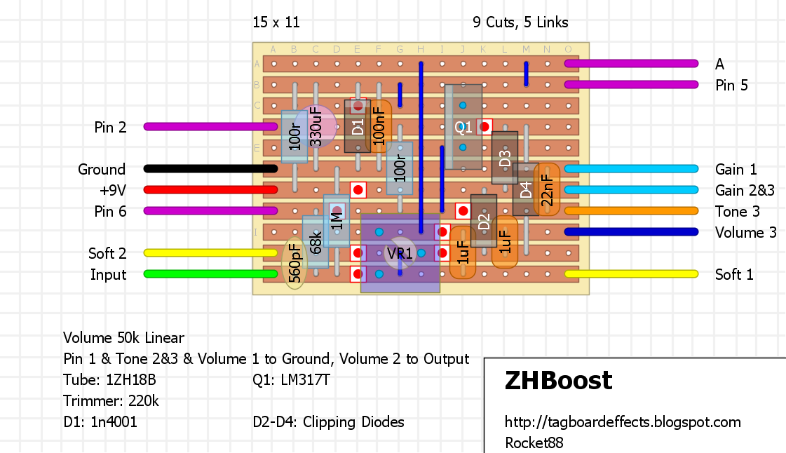
Modded with symmetrical clipping diodes to provide some more distortion, and a gain pot that controls how much the diodes are in the circuit, similar to the Germanium Giant, as well as a basic tone control.

Same layouts as above with the change to the power section. I decided to not include an onboard charge pump as it's just as easy to add one offboard with the available charge pump layouts on the site.
Non-modded layout:

Modded Layout with Asymmetrical Diodes:

Where'd you find the schematic for this?
ReplyDeleteFSB, I forgot to put a link to the post for this and the other tube circuits I posted last night. I'll put it up later.
DeleteAh ok I see it. Take a closer look at the power supply. The rectifier is for getting DC out of the AC supply. The supply shown in the schematic is 9VAC
ReplyDeleteDid you read the whole thread? I thought it was mentioned the switch to using DC instead of AC. I could be wrong. I'll look through it again when I get home.
DeleteOk so apparently the dude started with an AC supply and then just left the circuit all set up for AC when he switched to DC because it still worked. It's weird, and I don't really dig it but if it works and sounds good then that's cool
ReplyDeleteYeah it's bit strange. Using AC fine...doubler, rectification and filtering. But using DC? Doubler doesn't work, rectifier is redundant AND there's now 2 diode drops from 9V.
Deleteyea. i thought the same thing about the switch from AC to DC, but if it works, sounds good, and safe who am i to complain.
DeleteThe guy says he left the (now useless) doubler and rectifier for the "extra filtering".
DeleteI don't see a reason not to replace the whole thing with a small resistor and diode in series and a filter cap..
Anyway, the way it works with a DC supply means you're getting less than 9V to the tube with a 9V supply. No sense in wasting the space and diodes if you're using a DC supply. Also no need to get higher voltage rated caps since there isn't going to be doubling
For what it's worth, I'm not suggesting that this won't sound good at 9V.. the 12AT7 boost I made sounds amazing at 9V. I just don't see the point of wasting the space and components for the normal 9VDC supply?
very true. theoretically the rectifier should double the voltage to +18V, but that would happen if it was AC not DC, if i'm not mistaken.
Deletehe does state that it sounds better at +18V, as i would expect after looking at the datasheet for the tube.
idk, the schematic is verified, so i just made the layout to match it. i'm sure we could try messing with it, changing out the rectifier for the typical power filtering, just like you mentioned, and add an onboard voltage doubler. fuck it, i'll draw up a layout doing so if anyone wants to give it a shot.
since i don't have exams this week, i went through a bunch of posts dealing with tube pedals and small micro amps on FSB and DIYSB, kinda on a tube fix atm, that i plan on making a bunch of layouts for, including the zvex nano head. figured i'll do as many as i can before i've got to fade into the shadows starting this weekend, since i've got massive exams coming up.
Thank you Zach. Very much appreciated! For all that you do for us.
DeleteWill
Thanks for these Zach.I'm going to have a go at these and have already purchased a few tubes (not so cheap though). Not really dabbled in tubes yet but really want to build myself a decent tube amp head someday.
ReplyDeleteNo problem guys. I had some time today and completed the layouts with the revised power filtering Travis and I discussed above and will post them in a bit.
ReplyDeleteAs for the price of these tubs, in my searching on eBay they seem to go for ~$3usd a tube, so shouldn't be too expensive to build one of these or the other tube layouts I posted the same day.
As for the mini tube amps, it's a whole nother story. The transformers for the zvex nano head are not cheap, the PT being ~$46usd in my first look for the wiring labeling. So when all said and done I think the amps will run ~$100usd to build. The layout is nearly done, just have to finish the power section and it will be up, planning by Friday.
Personally I plan on building a few full blown tube amps, as many know already, but I think some of these mini tube heads would be worthwhile for pedal testing/demos and messing around at lower volume then my typical amps.
In my browsing i did see a lot of NOS tubes at some pretty hefty prices. I'm sure when i get the courage to build a tube amp head i'll be forking out the £/$s for some decent tubes.
Deleteagreed. these are the submini's so they're usually not that bad in price, even the NOS ones.
DeleteHey Zach is it just me or did I see an awesome layout for Zvex nano head only to have it disappear? A turret board layout would be killer for that to give room for the higher voltage caps and resistors....You rawk as always, looking forward to giving these tube pedals a go and to seeing the nano head layout again ....have a great day!
DeleteYes there was a layout posted on vero, but removed it for the time being due to some concerns, mostly due to the high voltages you'd deal with building it. I mean it is an amp with a power transformer that puts out 230V.
DeleteThere should have been enough room for all components, as you can get relatively normal/small sized high voltage caps, believe it or not.
But, in any event I may go and make a turretboard layout for it, just going to discuss with the guys if we feel it's a good idea, due to safety of everyone. I may. It go on the main page if I post it up. Don't want to have someone too inexperienced going to build it and getting hurt or worse dying do to an error or doing something they shouldn't.
That is what I thought. Safety first always. If you do post elsewhere on the blog let us know. Thanks so much for the reply. Have a great day!
DeletePS Rob Robinette has some great safety and warning pages. :)
https://robrobinette.com/Tube_Amp_Safety.htm
This comment has been removed by the author.
DeleteHey Zach Would it be possible to get the Zvex nano vero layout emailed to me or maybe a link to download. I just built a 5f1 and love it but need an amp to use at our vacation spot that is smaller and a tad more quiet or if it sounds good as a bench amp. If not no worries. Thanks for all your work either way!! RAWK!
Deletedv8fuzz@gmail.com
Hey Zach, The layouts without the rectifier do i just add +18v connection to the +9v on the board?
ReplyDeleteAlso, what are the gain and tone pot values?
Deletehey gavin, just saw your question. tbh i think that should be fine or even better is just use a charge pump to bump it from +9V to +18V
DeleteThanks Zach, What values do you reccomend for gain and tone pots
DeleteWill the non modded layout run at 9v?
ReplyDelete